Post Footing Sizing
A post footing’s purpose it to distribute the lateral and axial loads from the post into the ground to prevent the post from sinking under the weight of the fencing and any ice that builds up on it, and to keep the post plumb under lateral loads such as wind. As the footing is wider than the post, the forces are spread out over a larger area in the soil, allowing it to resist larger loads. Posts are allowed to be driven directly into the ground, or have the post hole backfilled and tamped with sand or other materials, but in those cases, only the width of the post can be used to resist the loads which is insufficient for most soil conditions. This guide only covers the use of concrete footings.
.
Concrete Specification
Minimum allowable strength of the concrete to be used is 2,000 psi per IBC §1807.3.3(1). Follow the manufacturer’s instructions if mixing at the site. Concrete mixed in the post hole or dry tamped and then watered cannot achieve the required strength. It is recommended to pour the concrete at least 1/2” above ground level and slope the concrete away from the post down to ground level to help shed water and extend the life of the post.
.
Footing Diameter
The minimum diameter of a post footing per IBC §1807.3.3(1) is 4” larger in diameter than a circular post, or 4” larger than the diagonal corner to corner distance for a square, rectangular or C shaped post. Hat channel posts would use 4” larger than the largest width. Other guides, including ASTM F567 call for much larger diameter footings, but these appear to be based on rules of thumb as opposed to structural calculations. As these guides are not referenced by the IBC, they can be neglected. Also, as the soil lateral bearing pressure increases with depth, a deeper, smaller diameter footing can carry more wind load than a shallower / larger diameter footing. This also reduces the amount of excavated soil and volume of concrete required.
.
Footing Depth
There is no minimum depth specified, but 2’ is considered the bare minimum. The depth should be at least 6” below the frost line provided by the local building official to prevent frost heaving of the post. Local codes may dictate a larger depth below the frost line. The IBC Post Footing Calculations are only valid to a maximum depth of 12’. If you need a deeper footing, consult a licensed Civil / Structural Engineer.
.
Post Footing Types
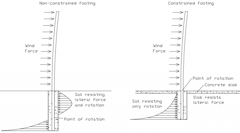
There are 2 types of post footings covered by the IBC: non-constrained and constrained.
Non-constrained is the most common condition where the footing is placed in the ground with undisturbed soil surrounding it so that only the soil pressure resists the lateral loads.
Constrained footings are footings surrounded by a large concrete slab (e.g. a parking lot) that keeps the top of the footing from moving under lateral loads. As the slab keeps the top of the footing from moving, the soil only has to resist the rotation, so the footing does not need to be as deep
The formulas below will be different depending on if the footing is non-constrained, or constrained.

.
Post Footing Calculation Process
Post footing sizing is an iterative process. As the soil lateral strength increases with depth, the deeper the footing, the more load it can support. Because of this, you can’t calculate the needed depth directly. You have to run through the calculations multiple times to arrive at the most economical depth.
You start with a Footing Depth, D and a Footing Diameter, b as starting values and calculate the depth specific soil strength, S1 for non-constrained footings, or S3 for constrained footings. You then use that value to back-calculate the Minimum Depth, d. You then compare the Footing Depth, D with the Minimum Depth, d. If D < d, the soil strength is insufficient and you must try again with a larger Footing Depth. Once you find a Footing Depth that is larger than the Minimum Depth, you can move to the next design step. If the Footing Depth is significantly more than the Minimum Depth, you can run the numbers again to get them closer together to minimize the Footing Depth for economy.
Larger diameter footings don’t need to be as deep, so if the depth is limited, (e.g. available equipment, rock layers, etc.) the diameter of the footing can be increased until the minimum depth is less than the achievable depth.
To verify that the soil is strong enough to support the weight, you then calculate the weight of the resulting footing, plus the weight of the fencing and any ice buildup and check that the bottom area of the footing is large enough to support the weight based on the soil conditions. If it’s not, you start the whole process over with a larger diameter footing and continue until you find the final depth and diameter values. The bottom of the footing can also be flared / bell-bottomed to increase the footing area.
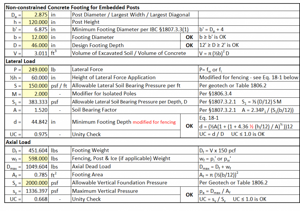
To prevent a lot of hand calculations, it is helpful to make a spreadsheet so you can quickly run through the steps to arrive at the most economical footing depth and diameter. A sample is shown at the bottom of this page.
.
Soil Strength Values
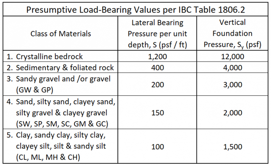
The Lateral Bearing Pressure, S and Vertical Foundation Pressure, Sy for the site should be determined by a Geotechnical Engineer, although the local building authority may have the information needed. For quoting and preliminary design, the values in the table below can be used, but significant savings can be realized on larger projects as these are conservative values.
Should local soil conditions be significantly different than those listed in Table 1806.2, then, with the approval of the building official, local experience can be employed in the design of foundations, particularly where actual load-bearing values are less than the allowable unit pressures given in the table.

.
Footing Variables
D = Footing Depth in feet. Start with the minimum value and adjust as necessary to find the most economical footing depth.
b = Footing Diameter in feet. Start with the minimum value and adjust if needed to either decrease the calculated minimum depth, d if desired, or if a larger value is needed once the vertical forces are found to be too high for the soil type.
S = Lateral bearing pressure per foot of depth (psf / ft) per geotechnical analysis, or IBC Table 1806.2.
P = Wind force (lbs)
Use P = fw‘ for Wind forces and P = fi for Wind on Ice on ice forces.
h = Post Height in feet.
½ h = Distance in feet from ground surface to the point of application of wind force, P.
The IBC formula uses h for the force’s application height, but ASCE 7 uses h for the overall fence height. To keep the variables consistent, the ½ h value is used in the formulas below as the post strength tables are based on the force being applied at the mid height of the post.
M = Modifier for isolated posts = 2.0. Per IBC §1086.3.4, isolated poles like fence posts can use a 2× factor on the soil lateral bearing pressure which will reduce the required footing size.
Allowable Lateral Soil Bearing Pressure for non-constrained footings, S1 = ⅓ D S M
Soil Bearing Factor, A = 2.34 P / (S1 b)
For non-constrained footings, meaning footings surrounded by undisturbed soil, the Minimum Depth, d formula is:

For constrained post footings, meaning footings surrounded by a large concrete slab (e.g. a parking lot) that keeps the top of the footing from moving, the Allowable Lateral Soil Bearing Pressure for constrained footings, S3 = D S M
The minimum depth formula for a constrained post footing is:

Once the Minimum Depth, d is determined that is less than or equal to the Footing Depth, D, calculate the weight of the footing, Df (lbs) to check if the axial load is acceptable.
.
Axial Loading
The area of the bottom of the footing, Af equals pi (π ≈ 3.14) times the footing radius in feet, squared.
Af = π (½ b)2
The Footing Volume, V equals the area, Af times the Footing Depth, D, in feet.
V = Af D
The weight of the footing, Df equals the volume, V times the typical concrete weight, 150 lb / ft3.
Df = 150 V
The total weight to be supported by the soil, Dmax is the footing weight, Df plus the maximum axial load, pi‘ for fencing plus ice loading, or pw‘ if ice loading is not applicable.
The maximum axial pressure on the soil, sy = Dmax / Af must be less than or equal to the Vertical Foundation Pressure, Sy. If sy > Sy, the soil cannot support the weight, and you have to start over with a larger Footing Diameter, b. Repeat this process until D ≥ d and sy ≤ Sy.
A sample spreadsheet is shown below that automates most of the work in this process. It takes time to make a spreadsheet, but once it’s done, you can size a footing in a couple of minutes.
.
Values are from the design example on the Post Sizing page.
.
1st pass – 9″ diameter footing, 48″ deep – footing depth is not sufficient.
2nd pass – 9″ diameter footing, 52″ deep – footing depth is now OK for the lateral load, but due to the extra weight of the deeper footing, the bottom area of the footing is now too small. A larger diameter footing is needed.
3rd pass – 12″ diameter footing, 46″ deep – footing depth and diameter are OK.

.
Next – Design Examples