Fence Design Variables
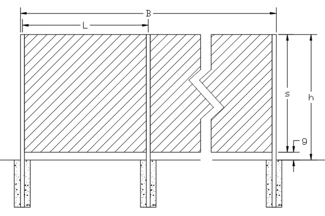
B = Length of straight line fence run in feet
h = Overall height of the fence in feet
g = Gap (if any) between the bottom of the fence and the ground in feet
s = h – g = Height of the fencing in feet
L = Post spacing in feet
B/s = Aspect Ratio
s/h = Clearance Ratio

—
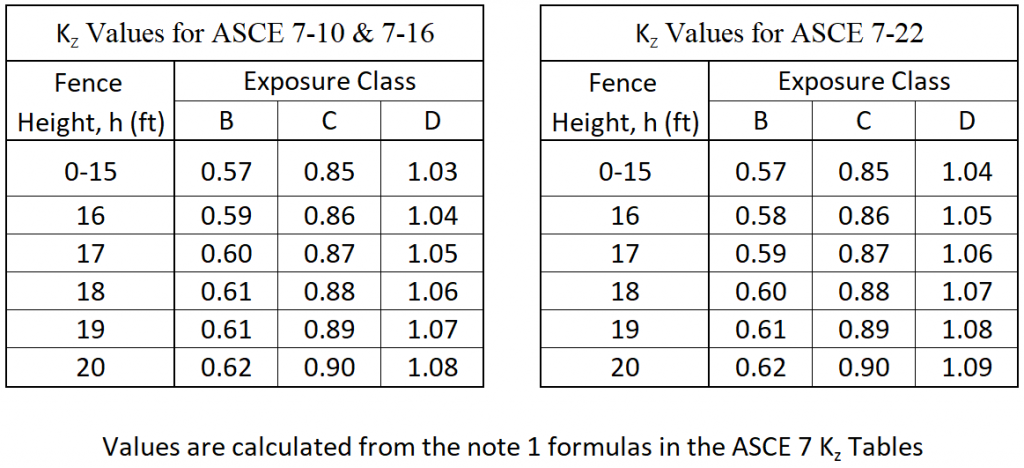
Velocity Pressure Exposure Coefficient, Kz
Wind forces increase based on the height of the fence. The Velocity Pressure Exposure Coefficient, Kz is used to adjust the wind force based on the fence height and Exposure Category of the installation site.

For open fencing, (ε ≤ 0.7) taller than 15′, use ½h to determine the Kz value. If ice loading raises the iced solidity ratio, ε’ greater than 0.7 for open fencing over 15′, use Kzw for Wind loading based on ½h and Kzi for Wind on Ice loading based on the full height, h. (see below for ε & ε’ definitions)
—
Wind and Ice variables
The wind force is mainly driven by the surface area and aerodynamics of the fencing material. The dead load of the fencing material affects the load bearing capacity of the post and the footing. Ice buildup can increase the wind area as well as add additional weight. The following variables are used to determine the forces the posts and footings must support.
—
Solidity Ratios, ε & ε’
Solidity Ratio, ε = The net area of the fencing divided by the gross area
Iced Solidity Ratio, ε’ = The net area of the iced fencing divided by the gross area
Gross area, Ag = Fencing height, s times the post spacing, L
Net area, An = The actual solid or iced area of the fencing material between the post centers.
For open fencing with wind screen, use just the wind screen area, neglecting the fencing in the un-iced condition.
For wind screen with flaps, still count it as solid as the flaps only let air through in one direction.
For ε or ε’ ≤ 0.7, the fence is considered open / lattice framework / single plane open frame.
For ε or ε’ > 0.7, the fence is considered a solid fence / solid wall.
—
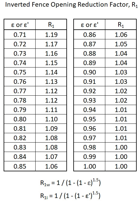
Inverted Fence Opening Reduction Factor, R1 (See Solid Wall Tables, Note 2)
This is a modifier for mostly solid fencing to adjust the wind force based on the open areas of the fencing. The Note 2 reduction factor is inverted for this guide to allow the solid and open fencing force calculations to use the same formulas. The value may be different in the normal condition, R1w vs the iced condition, R1i, depending on their respective Solidity Ratios, ε & ε’.
For an open fence (e.g. chain link) with a Solidity Ratio, ε or ε’ ≤ 0.7, R1 = 1.0.
For a solid fence with a Solidity Ratio, ε or ε’ = 1.0, R1 = 1.0.
For a mostly solid fence with a Solidity Ratio, ε > 0.7, R1 values are shown on the table below.

—
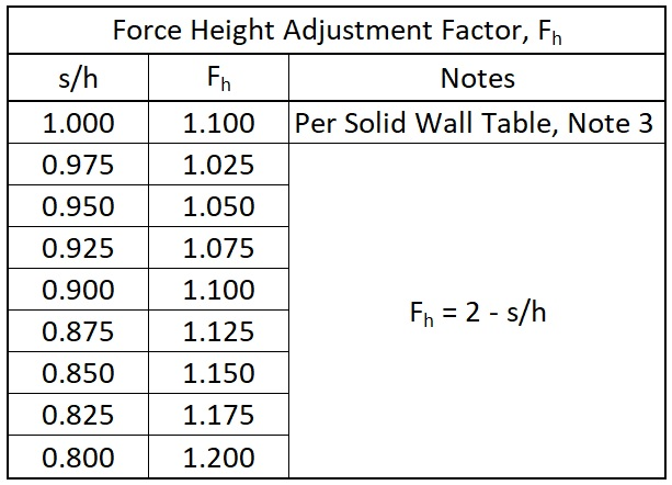
Force Height Adjustment Factor, Fh (see Solid Wall Tables, Note 3)
The post strength tables are based on the wind force being applied at the center of the post.
The Solid Wall Table, Note 3 requires the force to be applied 5% of the total height above the center of the post for fences with no gap at the bottom (s/h = 1.0).
For fences with gaps at the bottom, as the gap gets larger, the center of the fencing area, s rises above the center of the post, which raises the effective force application height.
The Force Height Adjustment Factor, Fh increases the calculated wind force to give equivalent results compared to raising the force application height.
For an open fence (e.g. chain link) with a Solidity Ratio, ε or ε’ ≤ 0.7, Fh = 1.0
For solid or mostly solid fencing the Fh values are shown in the table below.

—
Dead Load of fencing material, Dm
This is the weight per square foot of the fencing material. Take the weight of all the materials between the posts and divide it by the gross area.
—
Dead Load of Ice, Di
This is the weight per square foot of the ice that can build up on the fencing. The Chain Link Tables list estimated ice loading. For other fencing types, this would be calculated per ASCE 7 §10. See Design Examples.
The tables below show the ε, ε’, Cfw, Cfi, Dm and Di values for common fence types.
Chain Link Fencing
Mesh Sizes
2-3/8” 2-1/4” 2” 1-3/4” 1-1/2”
Note: Chain link with privacy slats or wind screen, ε and ε‘ should be set to 1.0, and the Cfw & Cfi values must be taken from the Case A & Case C Solid Wall Tables.
—
ASTM F2408 / F2589 / F2814 / F2957 – Ornamental / “Wrought Iron” Fencing
ASTM F2453 – Wire Mesh Fencing w/ openings ≤ than 6 in2
ASTM F2919 – Wire Mesh Fencing w/ openings > than 6 in2 – coming soon
ASTM F1267 / F2780 – Expanded Metal Fencing
—
Next – Cf Values