Wind Force Coefficient, Cf
The Wind Force Coefficient, Cf is an aerodynamic adjustment value based on the size and shape of the fencing material, the geometry of the fence, and the location of a given post in both the normal and iced conditions. Cfw is used for wind forces. Cfi is used for wind on ice forces.
If the fence is mostly open (ε or ε’ ≤ 0.7), the Cfw and Cfi values are based on the open fencing / single plane open frame table. The most common values are shown below.
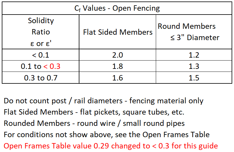
(ASCE 7 §29 – Open Frames Table)
If the fence is mostly open (ε & ε’ ≤ 0.7) in both the normal and iced condition (if applicable), the information below does not apply so you can skip to the next section. Lateral and Axial Loads
Solid and Mostly Solid Fencing
Case A – the wind direction is perpendicular to the fencing.
If the fence is solid or mostly solid (ε or ε’ > 0.7), the Cfw and Cfi values for posts away from ends and corners are based on the Case A Solid Wall Table. The most common values are shown below. If the Aspect Ratio, B/s and/or Clerance Ratio, s/h fall between the values shown on the table below, use the highest adjacent Cf value or interpolate.
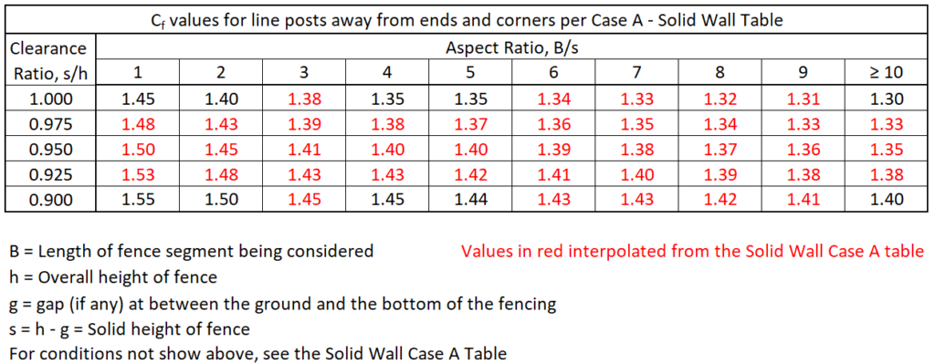
(ASCE 7 §29 – Solid Wall Tables)
Case C – the wind is at a 45 degree angle to the fencing.
If the fence is solid or mostly solid (ε or ε’ > 0.7), the Cfw and Cfi values increase as you approach an end or corner and are based on the Case C Solid Wall Table. The variable Cf wind regions that need to be considered are based on the Aspect Ratio, B/s of the straight fence run being designed. The width of each wind region is the fencing height, s. (e.g. for a 6′ tall fencing height, each wind region would be 6′ wide)
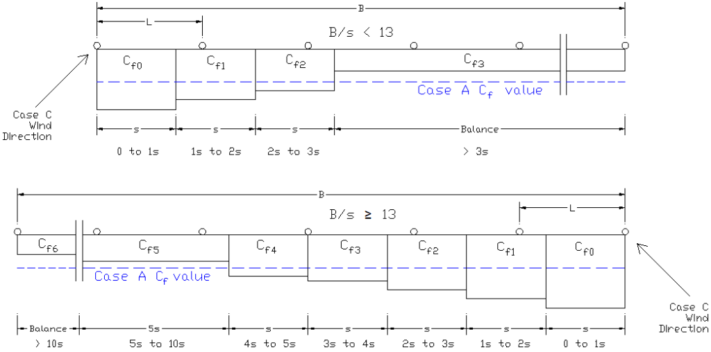
If the Aspect Ratio, B/s falls between the values shown on the table below, use the highest Cf value of the two or interpolate. Values with an * next to them are subject to the Return Corner Reduction Factor, R3 if applicable.
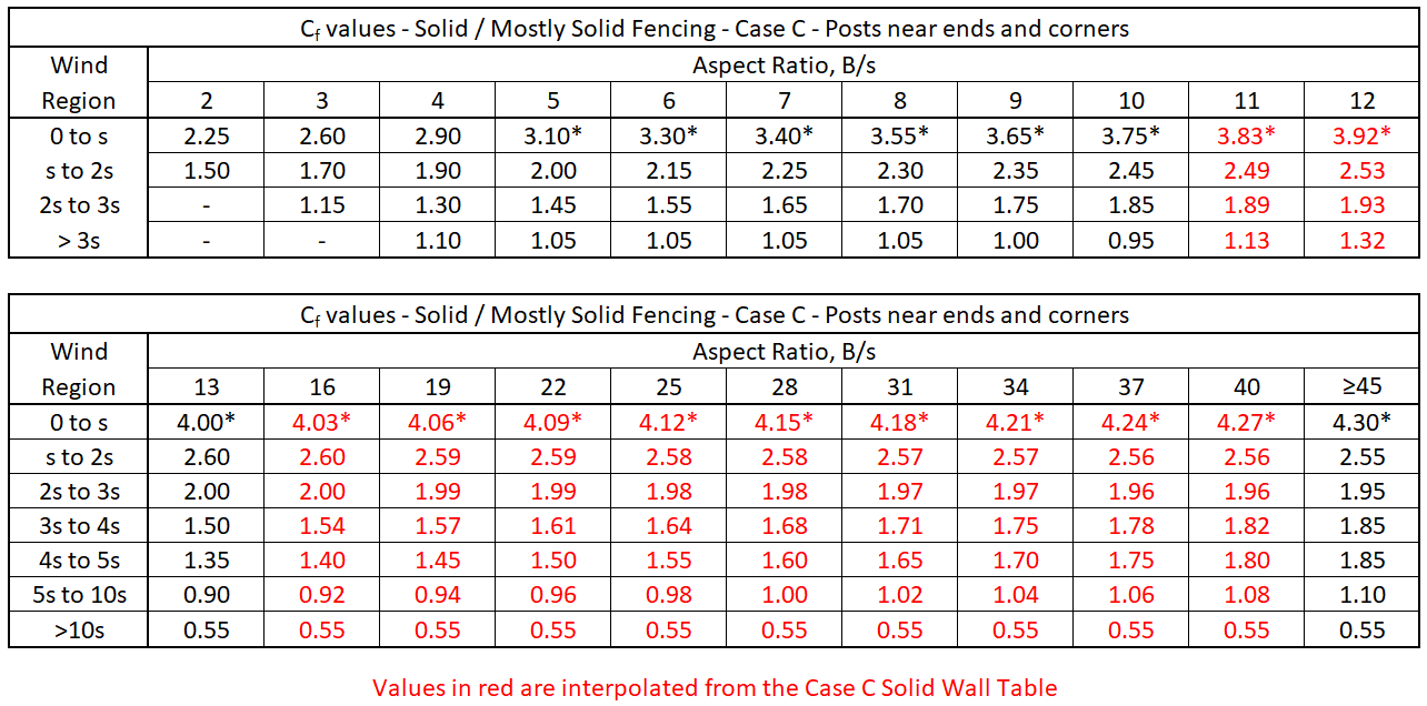
(ASCE 7 §29 – Solid Wall Tables)
_
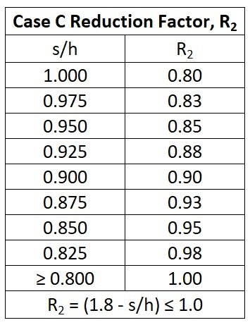
Case C Reduction Factor, R2 (See Solid Wall Tables, Note 4)
This is a modifier for solid or mostly solid fencing to adjust the Case C Cf values based on any gap between the ground and the bottom of the fencing material.
The Clearance Ratio, s/h determines which R2 value is to be used. The R2 value can be selected from the table below, or calculated directly from the formula at the bottom of the table.
_
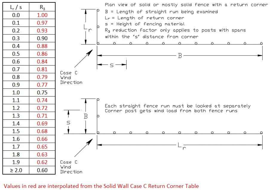
Return Corner Reduction Factor, R3 (see Solid Wall Tables, Case C, Return Corners)
This is a modifier for solid or mostly solid fencing to adjust the Case C Cf value for the “0 to s” wind region closest to an end or corner. The R3 values are shown on the table below based on the Return Corner Length, Lr to fencing height, s ratio. If the Lr / s value falls between two values on the table, use the highest value, or interpolate.
If there is no return corner, or if the Aspect Ratio, B/s is < 5, R3 = 1.0.
_
Equivalent Cf values for Posts near ends and corners
For solid or mostly solid fencing, (ε or ε’ > 0.7) near ends or corners, the spans for each post will have variable loading, so determining the equivalent Cf value for a given fence post takes extra steps.
The fence layout near the ends and corners needs to be sketched, either in a drawing program like AutoCAD or by hand on graph paper, showing the post spacings and the Cf zones. You can either do this just for the longest fence run to save time, or for every fence run for the most economical design.
The Cf values near ends and corners need to be adjusted with the Case C Adjustment Factor, R2. The 0 to s region also needs to be adjusted with the Return Corner Reduction Factor, R3.
If just designing to the worst case post, this is typically the post next to the end post on the longest run. If both ends of the longest run have return corners, check the end with the shortest return corner. A shorter fence run without a return corner may have a higher equivalent post Cf value.
_
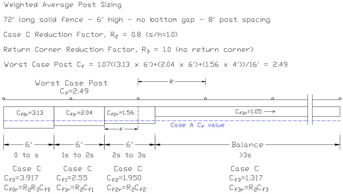
Weighted Average Method
The simplest way determine the equivalent Cf value of the worst case post is to calculate a weighted average of all the Cf values applied on each side of the post based on the zone lengths. This estimated value will range from around -6% to +11% of the actual equivalent Cf value for the post, so a 7% adder is used to make sure the weighted average value is above the actual value.
Example – The post next the end post gets 6′ of Cf0r = 3.13, 6′ of Cf1r = 2.04 and 4′ of Cf2r = 1.56. Equivalent Post Cf = 1.07 × ((6′ × 3.13) + (6′ × 2.04) + (4′ × 1.56)) / (2 × 8) = 2.49.
If using the conservative Weighted Average Method, you can skip to the next section:
_
Summing Moments Method
The most accurate way to determine the equivalent Cf value for a post is to sum the moments about the posts on either side of the post being examined. This is a more involved process, but provides the most economical Cf values.
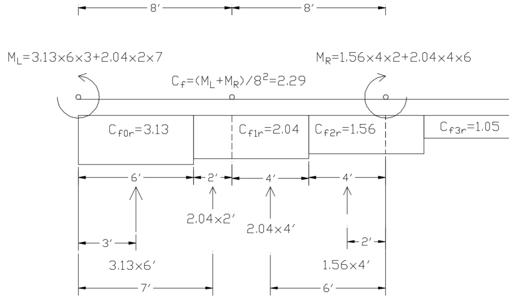
For the left span, for each Cf zone, measure the distance from the left post to the center of the Cf zone portion on that span (the moment arm), times the length of the zone portion on that span, times the Cf value to get the moment about the left post for each zone. Add these together to get the total moment about the left post, ML. Do the same for the right span, measuring from the right post to get MR.
If the Post Spacing, L is the same on each side of the post in question, the equivalent Cf value for that post = (ML + MR) ÷ L2
If the post spacing is different on each side of the post in question, with the left post spacing being LL and the right post spacing being LR, the equivalent Cf value for that post = (ML ÷ LL2) + (MR ÷ LR2)
Summing moments example using the same geometry as the weighted average example:
ML = 3.13 Cf value × 6′ zone length × 3′ moment arm + 2.07 Cf value × 2′ zone length on that span × 7′ moment arm = 85.32
MR = 1.56 Cf value × 4′ zone length on that span × 2′ moment arm + 2.04 Cf value × 4′ zone length on that span × 6′ moment arm = 61.44
Equivalent Cf = (85.32 + 61.44) ÷ (8×8) = 2.29. This is about 9% less than the weighted average example above, but could be as much as 19% less depending on the fence geometry.

_
Next – Lateral and Axial Loads